One of the toughest things I’ve had to “discover” is information about gas lines, gas valves, etc. Not having gone through gas plumbing school where I’m guessing some of this is taught, I have found it difficult to locate information and help for us do it yourselfers. Of course that could be because gas is dangerous and if done wrong can render disasterous results. Please read disclaimer #2 on my home page carefully before you consider any of the following information.
Pipes and Nipples
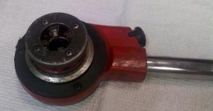 When I’m building cook trailers I tend to use 3/4″ black pipe. I have found that 1/2″ pipe sometimes limits the required amount of gas on higher BTU appliances. 3/4″ pipe seems to always work well. There are tables you can use to determine pipe size based on the length of pipe and the BTU’s of your appliances (see reference section below). Black pipe can be purchased almost anywhere. I get mine from a steel retailer and it comes in 21 foot lengths with no threads on it. One of my first investments was a hand pipe threader (picture on right) from Harbor Freight so I can put threads on 3/4″ black pipe. I can thread almost any pipe as long as it is at least six inches long.
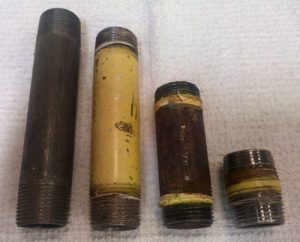 For pipe shorter than about six inches I go to my local plumbing supply store and buy “nipples” which come in a wide assortment of lengths with threads on both ends. I have a big box of nipples that I draw from when plumbing my trailers.
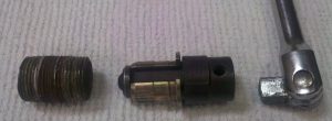 The picture at the right is a cool nipple extraction tool like the ones found here at Sears. It connects to a standard socket wrench and fits inside a 3/4″ pipe. As you turn the wrench it expands the tool and grabs the inside of the pipe. It saves a lot of screwed up threads when removing short nipples.
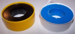 When connecting pipes I like to use just Teflon (or “thread seal”) tape. For gas you must use either the yellow or pink tape. It’s probably twice as thick as the white stuff and is meant specifically for gas fittings. You can find more information on it here. I have tried some of the pastes such as Tru-Blue but have not had a good success rate.
Manifolds
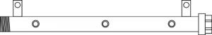 If a gas line goes to more than one valve then I usually build a manifold for it. My manifolds are just a piece of 3/4″ black pipe with threads on one end and a cap on the other. I also weld pieces of strap to it with holes drilled for mounting screws. Be careful to ensure any welds do not jeapordize the integrity of the pipe to hold gas. Once the manifold has taken shape I drill the top of it with 21/64″ holes for my valves. I then tap the holes with a 1/8″ pipe tap.
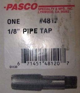 Some notes about pipe taps: Although pipe taps are measured in inches, you generally cannot match them up to a tape measurer. My understanding is that pip sizes were originally based on the inside diameter of the pipe. As technology has been enhanced, the inside diameter has changed but the outside diameter has remained constant for the purpose of standard fittings. Therefore, a 1/8 inch pipe tap is actually no where near 1/8 inch in size. Also, pipe taps are “tapered”. This means they get bigger as the tap threads goes deeper. So when tapping with my 1/8″ pipe tap, I only go about halfway down the tap. If you go all the way through then the threads will be too big and you will not be able to seal your valves. For the 1/8 inch tap I pre-drill with a size “R” (0.339″) drill bit. You can find a list of common taps and drill sizes here.
Valves
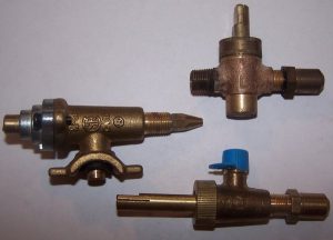 Valves are an easy way to control gas burners. With valves the burner temperature is set manually by turning the control knob. Pictured on the right are three different types of valves. The one on the left is a common valve used in home BBQ units. It seals to the manifold by using a rubber grommet and clamping to the manifold pipe.
The valve on the top is one type of commercial gas valve. It has a 1/8″ tapered pipe male thread on the left side, an orifice on the right side, and the knob stem shown coming out of the top.
The valve on the bottom is the most common type of valve in use today. It is shown here with a 1/8″ tapered pipe male thread on the top (covered with a blue plastic cap for shipping), a knob stem on the left, and an orifice on the right.
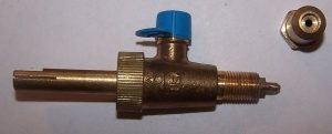 Here is a picture of the standard valve with the orifice removed. The orifice controls the final gas flow to your burners. Orifices must be sized according to the type of gas used and the BTU’s needed for a burner. The valve shown here has a “needle” or stem at the end of the valve so the orifice hole can be adjusted by tightening it down further. So with this valve and orifice, you can connect it and then adjust the gas output by loosening or tightening the orifice. If you don’t use the needle valve approach you can get orifices with pre-sized holes in them. I personally prefer to pre-drill the hole to the right size and make it non-adjustable. Then ongoing tuning is never needed.
Orifices
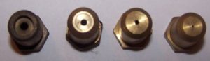 Here are some standard orifices arranged so you can see the hole in the end. The dark one on the left was used in a high BTU burner. It has the largest hole (#37 drill or .104″) of the samples so it provides the most gas to the burner. The next one is a standard natural gas orifice. Natural gas requires more flow than propane, therefore the holes are bigger. This one has a #45 drill or .082″ hole. The third one from the left is a standard propane orifice which has a #54 drill hole or .055″. The one on the right has a very tiny hole which could be used as a pilot light. I buy them with this size and then drill them out to what I need. So it’s
 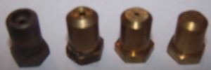 easy to take the orifices off a propane device, drill them out larger and place them back on to convert it to a natural gas appliance. To convert a natural gas appliance to propane requires you to get new orifices as then need a smaller hole. If you get real lucky and have an adjustable orifice then it’s very easy to just adjust it accordingly.
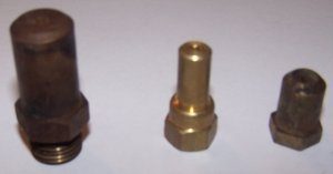 Here is a picture of a few other orifices from other appliances. The one on the right is a standard orifice with a 1/8″ female pipe thread on the inside. The middle one fits almost the same but was made longer to ensure it doesn’t slip out of the burner orifice hole during travel. The one on the left is from a commercial convection oven that needed some serious fire power.
Assembly and Testing
Before we move on, one more note about the valves. Once I mount the valves on my manifold and bolt the manifold in place, I usually create a “cover” plate that has holes in it for the knob ends to go through. When you do this be careful that the cover plate DOES NOT rub on the valve knob shaft. The shaft should turn free and clear without any obstruction. The actual gas flow inside the valve is controlled by a cone shaped piece connected to the knob stem. If you put any pressure downward or sideways on the stem it will make it so the cones doesn’t seat and the gas will always run and your burner will never shut off. It also will quickly wear a significant groove in the shaft as the valve shaft as it turns.
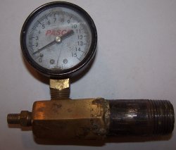 Once all your gas lines are ready and your manifold has been built and valves installed, you can (and should) pressure test. This will let you know if you have any leaks. The picture at the left is my pressure tester. It consists of a 3/4″ pipe with an air pressure gauge and a valve stem attached to it. I connect this to the end where the gas comes in and use a bicycle pump to fill it to between 3-5 lbs of pressure. Your system should hold the pressure for days. If not, check it all again. If you use unions the tighten them harder. You can also use soapy water and a small paint brush around each coupling to locate leaks. Make sure it is solid before you connect it to the gas
Burners
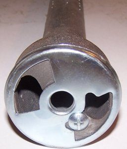 The orifice goes directly into the end of your burners. Here is a picture of one such burner. Each burner usually has an adjustable plate (see the Phillips screw) by which you can adjust the air to gas ratio. I’m no expert on what to look for when adjusting this. There are several good write-ups on the web that explain it better than I can here. I just know that if you close off the air too much then the gas burns way to rich and whatever is on top of the burner turns black with soot. Therefore I lean towards much more open than closed.

Gas and Air Mixture
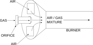 For a burner to work properly it must have a balanced mixture of gas and air. The gas is controlled by the size of the hole in the orifice. That usually feeds directly into the end of a burner which has adjustable vents to let in air. The action of the gas flowing into the burner in a specific direction causes a vacuum which pulls air in from the air vents. The gas and air then mix and proceed on to the burner jets where they are ignited.
If there is not enough gas then the flame will be too low. If there is not enough air then the flame will burn “rich”, use much more gas than is needed and leave a sooty film on everything. It is critical to adjust the amount of gas (through the size of the orifice opening), and the amount of air (by adjusting the vent openings) to get the right mix.
Knobs
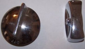
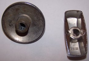 The knobs can be the most expensive part of the whole process. Good chrome plated steel knobs tend to be pricey. They are also the first to get lost on a trailer. There is a lot of different types available including many plastic ones. I tend to like the steel ones as they have a set screw and I don’t loose as many.
Pilot Lights
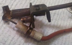 There are many different configurations that can be used for a pilot light. The picture on the right shows a pilot assembly. The red wire on the bottom is for an electric spark starter. The actual pilot gas line and pilot orifice are at the top of the assembly. The copper tube in the center is where a thermocoupler temperature sensor is inserted for a pilot safety valve. Also note that on the top of the pilot burner there is a piece of metal (left side of picture) that “routes” or points the flame towards the burner.
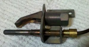 Here is another type of pilot. This one does not have an ignition wire which would indicate that it must be lit manually. It also has a thermocoupler sensor in it. The actual gas line would be connected to the upper fitting but is not present in this picture.
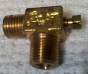 This is a pilot adjustment valve. The male threads shown here on the bottom are 1/8″ tapered pipe threads, the same as might be found on the burner valves. The male thread to the left is made to connect a squeeze ring connection which goes to the pilot light burner. The small screw shown on the right hand side is used to adjust the height of the pilot flame.
Simple Burner Configuration
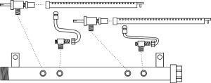 Shown to the left is a simple griddle burner configuration. It consists of an incoming pipe which doubles as a manifold, two burners and two pilot lights. In this configuration you must light the burner manually when the gas is turned on and there is no safety shutoff if the wind extinguishes the pilot flames. The heat level is controlled by the burner valves. The pilots remain lit as long as gas is present so the burners can be turned off when not in use.
The following steps should be used to test the configuration shown:
- Connect an air pressure gauge to the end of the manifold.
- Turn the screws on the pilot adjustment valves all the way clockwise to close them.
- Turn off the control valves by turning the knobs flat horizontally.
- Inflate the manifold with air to about 3 PSI.
- Use a spray bottle of water with a little soap and spray around all the pipe connections. If bubbles appear then correct the issue and re-test until there are no leaks.
- Once testing has been completed you can remove the pressure gauge and connect the regulator and gas line to the manifold.
- With the gas turned on, slowly turn each pilot adjustment screw counter-clockwise while lighting the pilot with a gas ignitor. Adjust the pilot levels so each is about 1″ high.
- One at a time, turn on a burner full on (knob straight up and down vertically). Adjust the maximum flame height by tightening or loosening the orifice (this assumes you are using a needle valve orifice). Repeat for each burner.
Pilot Safety Valves
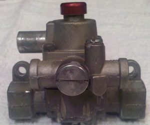 Pictured here is the most common pilot safety in use. It is a Robertshaw model TS-11. On the very bottom of the piece there is a 3/8″ line in and line out for the gas line that is going to your burners. Just above that to the left and right of the large center screw, is a smaller gas line in and out for the pilot light gas line. Just above that on the left side is a connection for a thermocoupler that goes to the pilot.
Here is how it works: When the gas is turned on nothing is allowed to pass this valve to either the burner or the pilot light. When the red button (pictured at the top of the control) is pressed, gas flows only from the pilot gas line to the pilot to allow the pilot light to be lit. Once lit you must continue to hold the red button until the heat from the pilot travels down the thermocoupler back the TS-11. Once the heat is sensed at this control then you can let up on the red button and the pilot will remain lit. Once the heat is sensed then the main gas line is also opened allowing the burners to light. If the pilot should ever go out, then the gas to the burner and pilot is stopped.
Thermocouplers
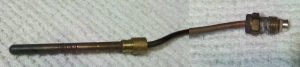 This is a thermocoupler. You can get these in many different lengths. The middle portion has been removed from the picture here so that you can see both ends. The long end sits over a flame in a pilot or a burner. The screw end goes into a control valve such as a TS-11. The wire connecting the two is usually filled with mercury. It picks up the heat from the flame and transfers that heat to the other end so the control can sense it. Thermocouples are replaceable. If your safety valve is not kicking in when a flame is present you can try replacing the thermocouple to see if that resolves the issue. Sometimes, as thermocouples get older you may have to turn up the pilot flame to get enough heat to transfer to the control so that it kicks on.
Thermostats
 Thermostats are used to control the temperature for ovens and griddles. When you just use a valve, you control the temperature by adjusting how far the valve is open. When using a thermostat, the burner is turned on and off to control the temperature. Therefore, to use a thermostat you must have a pilot light. In most cases you should also be using a pilot safety valve as well.
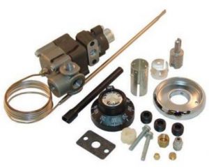
There are many different types of thermostats. All of the newer ones are electric. Since most of my equipment is used where there is no electricity, I prefer the older all-mechanical thermostats.
Thermostats have a built-in thermocoupler type thermometer. These cannot be replaced. If the line to the thermometer is damaged then the entire control must be replaced. The thermometer line must be located in a place where the proper heat can be measured. For an oven it is normally mounted near the top on a side wall. Ovens use metal clips to space it a little so it does not touch the oven walls. For a griddle it is normally mounted to the underside of the griddle plate. Most tuck it under a small piece of angle iron that is welded to the bottom of the griddle.
Orifice Connectors
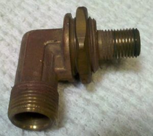 As I showed above, orifices fit directly on the end of the valves which can then go right into the burners. When using thermostats, the orifices are connected through an elbow such as the one pictured on the left. These usually have a standard 3/8″ squeeze ring fitting (shown on the bottom), and a standard orifice thread (shown on the right). They also have a larger thread and nut just above the orifice thread by which they can be secured to a holding plate.
Full Burner Configuration
In a full burner configuration the main gas is split for the pilot light and the thermostat. The main line then comes into the thermostat and from the thermostat goes into the main line on the pilot safety valve. The pilot split from the main line also goes into the pilot safety valve. Out of the pilot safety valve the pilot line goes to a pilot adjustment valve and then to the pilot light. The main line goes either directly to a burner orifice or to a manifold that branches into multiple orifices. The orifices are connected to the burners. The thermocoupler from the pilot safety goes to the pilot lights. The thermometer from the thermostat is mounted where it can monitor the temperature.
Summary
So there’s my wealth of information on gas. Over the year’s I’ve learned that it’s really not as “mysterious” as people paint it to be. I find some places to be very helpful and others that won’t even sell to me. But just by playing around with it I can now take almost any gas appliance and convert it from Natural to Propane or the other way around. When building cook trailers with whatever you can find these skills come in rather handy. I hope this has proven somewhat useful information.
Reference Information
www.andersonforrester.com
LP /Natural Gas Orifice Drill Table
Resizing Orifices for Propane from Natural Gas
Propane Gas Pipe Sizings
Gas Orifice Capacity Chart by BTU’s
OSHA LP-Gas Regulations
RegO Products LP-Gas Serviceman’s Manual

Recent Comments